Thermal Management-On the Design of the Cooling Scheme of the Homogeneous Plate
Background:
The cooling methods of the existing modules are mainly water cooling and air cooling; among them, air cooling takes up a large volume while the cooling effect is not ideal; one of the main reasons is that the convective heat transfer coefficient on the battery surface is low and the heat exchange area Limited by the surface area of the cell, in order to allow the air to take away the heat of the battery in time, the temperature difference between the cell and the air must be large enough, which makes the temperature of the cell higher, and reduces the life of the cell. Self-discharge is quite unfavorable; therefore, we decided to develop a new air-cooled heat dissipation structure using the technical principle of the uniform temperature plate. This type of heat dissipation structure maximizes the use of the existing module structure and the volume of the battery pack, and at the same time improves the heat dissipation effect of the cell, and reduces the cell temperature from the level of the existing air-cooled module to a lower level.
Brief introduction to the principle and characteristics of the temperature equalization plate:
The vapor chamber is a plate surrounded by two copper plates with a cavity inside; the inner wall of the cavity has a capillary structure and supporting copper pillars. At the same time, the cavity is evacuated and filled with a certain amount of working fluid. The zone utilizes the phase change of the working fluid from liquid to gas to absorb heat, and after being condensed to release heat at the condensing end, the phase changes again, from gas to liquid, and then returns to the evaporation zone by the capillary force of the capillary structure. The principle is basically the same as the heat pipe. The advantage is that the temperature on the surface of the entire temperature equalizing plate is very uniform, and the heat source with a small area and high heat flux density can be expanded in disguise, reducing the heat flux density, and then cooling it.
An Introduction:
Taking into account the different size and space constraints of the modules, we have designed two different cooling schemes for the uniform temperature plate: design 1 of the uniform temperature plate cooling scheme.
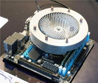
Each two cells (6Ah) in the module share a temperature equalizing plate, and the upper double surface of the equalizing plate is welded with heat sink. The heat sink has a dedicated air duct and is cooled by 25℃ air. The size of the temperature equalizing plate is 60*160, and the thickness is 5mm (or thinner) in order to make full use of the width of the existing air duct between the cells.
If it is assumed that a module has 18 batteries, a total of 0.39KWh electricity (refer to JH and gw projects). The design structure is shown in the figure below:
Flow field and thermal simulation:
In order to verify the heat dissipation capability of the heat sink, it is necessary to simulate the heat dissipation capability of the heat sink. Use flotherm 9.3 software for simulation.
Simulation boundary conditions:
1. Assuming that the inlet air velocity is 2m/s, the inlet position is 100mm in front of the radiator, and the outlet is 50mm behind the radiator; the total air volume of a module is 0.93m³/min (32.78CFM)
2. In the steady state simulation, the thermal power of the bottom surface of the heat sink is 3.5W; this power is the heating power of the 6Ah cell at 5C discharge, and the 5C discharge is calculated according to the customer's working conditions.
3. The air duct does not leak air, all the air entering from the inlet flows through the radiator and then flows out from the outlet, the outlet pressure is 0
4. Regardless of radiative heat transfer, the wall of the solution domain is set as an adiabatic wall.
Simulation initial conditions:
1. Inlet air is the air in the cabin, assuming a constant 25℃
2. The initial temperature of the heat sink is 25°C (steady state simulation)
Model settings:
The radiator material is Al 6061
The bottom surface of the radiator is heated with constant power, 3.5W
The flow field model is turbulent.