Charging pile thermal cooling
Compared with other power supplies, the system heat dissipation of the charging pile is much larger, and the requirements for the thermal design of the system are extremely strict. The power range of DC charging pile is 30kW, 60kW and 120kw, and the efficiency is generally about 95%. Then 5% of it will be converted into heat loss, and the heat loss will be 1.5KW, 3KW and 6kW. For outdoor equipment, these heat must be discharged from the equipment, otherwise the aging of the equipment will be accelerated. At the same time, waterproof and dustproof treatment shall be done to prevent short circuit and signal disorder of electronic equipment.

At present, there are four commonly used cooling modes of charging pile: natural cooling (mainly relying on heat sink), forced air cooling, liquid cooling and air conditioning. Due to the influence of volume, cost, reliability and other factors, at present, most companies use forced air cooling. Then, this is bound to bring dust, corrosive gas, moisture and other interference.

The heat dissipation of the charging pile is divided into module heat dissipation and the overall heat dissipation of the chassis. Because the charging module is built in, the protective measures are mainly reflected in the chassis design. The simplest and economical design is to make the louver type at the air inlet and outlet of the box, and then add a fan at the air outlet to remove the heat discharged by the module fan. This method can play a certain protective role. It is inevitable that dust and moisture will enter over a long time.

If you want better protection effect, use closed cold and hot isolation air duct to isolate the inside: the middle partition plate completely separates the cold and hot fluids, and effectively cools down through the heat conduction carrier and the top fan. The louver filter screen group is selected for the air inlet and outlet at both ends to effectively prevent water and dust.

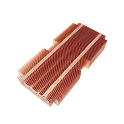
The heat conduction carrier is composed of a tube shell, a liquid absorption core, an end cover and fins × After the negative pressure of (10-1 ~ 10-4) Pa is filled with an appropriate amount of working liquid, the wick capillary porous material close to the inner wall of the pipe is filled with liquid and sealed. One end of the pipe is the evaporation section (heating section) and the other end is the condensation section (cooling section). According to the application needs, an insulation section can be arranged between the two sections.
When one end of the heat pipe is heated, the liquid in the core evaporates and vaporizes, the steam flows to the other end under a small pressure difference to release heat and condense into liquid, and the liquid flows back to the evaporation section along the porous material under the action of capillary force. In this cycle, heat is transferred from one end of the tube to the other. And there is a top fan to take away the heat.