Cooling technology that can improve heat dissipation and its working principle
Now, let us enter the ultimate problem that everyone cares about: heat dissipation.
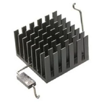
heat fin
The heat sink is a passive heat transfer device. When transferring heat from the IC package to the surrounding environment, its thermal resistance is much smaller than the parallel thermal resistance from the package to the environment caused by thermal convection and thermal radiation.
Figure 1 shows the thermal resistance model of the N-fin heat sink (N is the number of Fin), where the thermal interface material (TIM) is connected to the top of the package. We need TIM to improve the contact between the package and the heat sink, so the effective thermal resistance of the heat sink needs to include the thermal resistance of the TIM.
The equivalent resistance of the heat sink is approximately equal to the resistance of the TIM plus the resistance at the bottom of the heat sink, and the resistance of the heat sink divided by the number N. Since the area of the heat sink can be larger than the top surface area of the package, its heat convection and heat radiation resistance can be smaller than the heat convection and heat radiation resistance of the top surface of the package. In addition, if the resistance is divided by the number of heat sink Fin, an improvement of N times can be achieved. However, for a given heat sink substrate area, when the increase in Fin is higher than a certain amount, it will eventually cause the thermal resistance of each Fin to increase: this is because the heat sinks start to approach each other and reduce the effective heat transfer coefficient. . And because these thermal resistances directly increase the effective thermal resistance of the heat sink, it is very important to choose high thermal conductivity materials for the heat sink and TIM in order to improve the overall performance of the heat sink.
heat sink
Another technique for cooling electronic systems is to use thermal vias and heat sinks to spread more heat from the IC to the back of the PCB. The heat dissipation holes placed under the IC can significantly reduce the thermal resistance of the PCB and help guide heat to the heat dissipation plate placed on the bottom of the PCB. The radiator is made of high thermal conductivity material (such as graphite) and has a larger surface area to improve heat dissipation。
fan
When passive heat sinks or radiators are not enough to eliminate heat, consumer electronic systems such as desktop computers, notebook computers, projectors, etc. can also use electronic fans to dissipate heat. Fans use electric motors and require electricity to actively move airflow around the system to remove heat. This may cause audio noise, so noise and reliability issues need to be considered when choosing a fan. Many fans today can use pulse width modulation (PWM) signals to control the speed, so you can design a thermal management system to dynamically adjust the fan speed based on the system temperature.
Heat pipe
The heat pipe is a heat transfer device that uses the principles of heat conduction and phase change to transfer heat between solid components. The phase change of the radiator pipe usually refers to the process in which the liquid reaches the boiling point at the evaporation end and vaporizes and spreads into the pipe as a gas. After it reaches the cold end, it condenses and releases heat, and then the liquid flows back to the evaporation end by capillary action. In the movement of transferring heat from the evaporating end to the condensing end, this process will be repeated continuously. Heat pipes are also widely used in consumer electronic systems, such as computers, tablets and smartphones.
Dynamic throttling
Finally, as electrical engineers, we can indeed use various power throttling techniques to control the power consumption of the system, but this usually reduces system performance. Our goal is to enable customers to get the best user experience while weighing performance as much as possible. Many electronic systems now use thermal sensors throughout the PCB, allowing the on-board processor to monitor the temperature in the system and make dynamic throttling decisions when the temperature rises. As electrical engineers, we naturally understand the various power curves of the system. We can achieve our expectations by turning on the fan, reducing functions, disabling different parts of the system, or limiting the clock speed when the system temperature reaches different temperature thresholds.